TIVA Launchpad Pin Assignments A Tiva™
TM4C123GH6PM was used as the microcontroller.

| Pin | Type | Purpose |
|---|---|---|
| PB0 | Digital Output | Serial Data for SR8 |
| PB2 | Digital Output | Register Clock for SR8 |
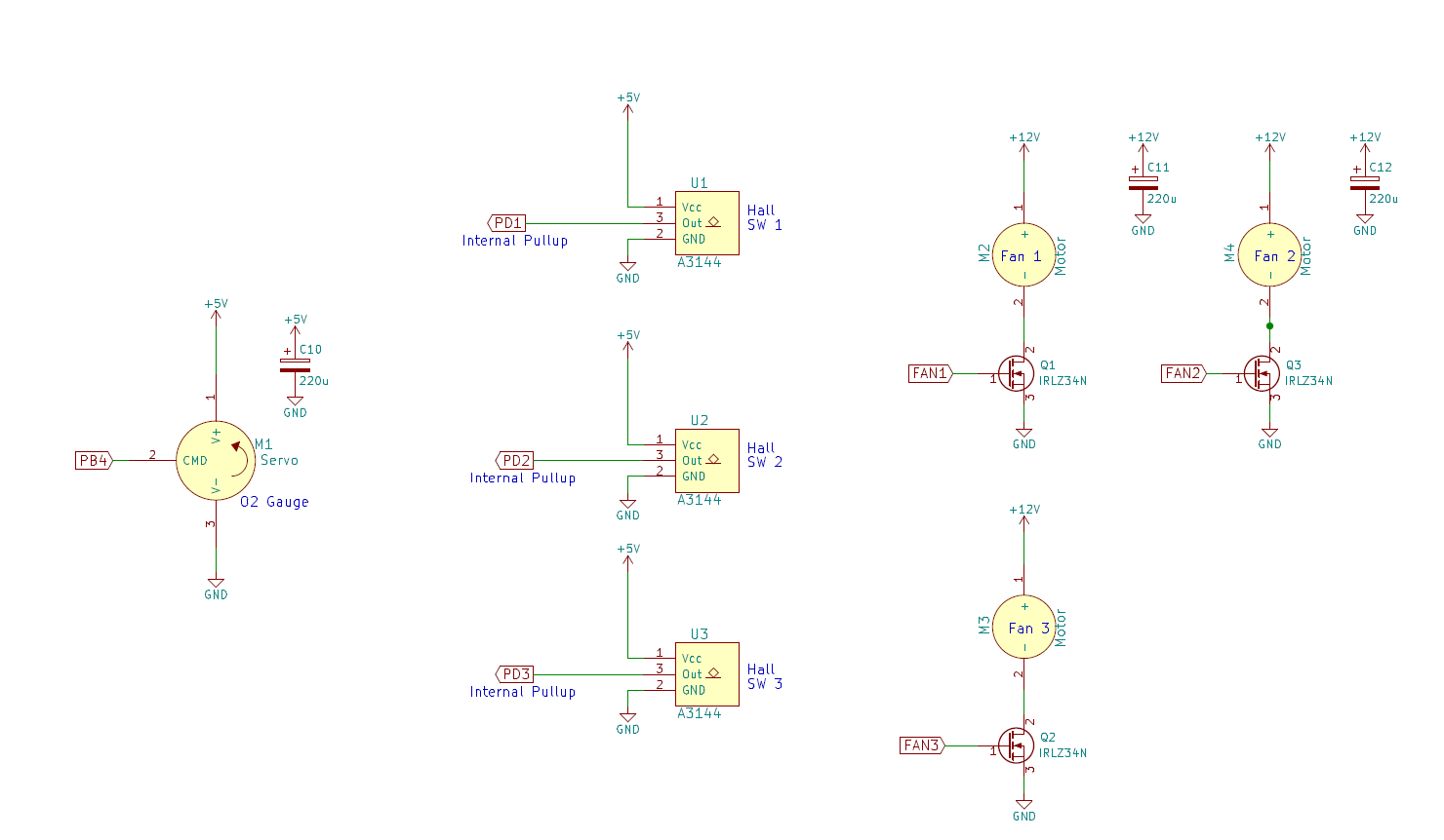
| PB4 | PWM | Servo control - Oxygen Gauge |
| PB5 | PWM | Servo control - Power Gauge |
| PB6 | PWM | Servo control - Cannon |
| PB7 | PWM | Servo control - Rocket Timer |
| PA2 | Digital Output | Serial Data for SR24 |
| PA3 | Digital Output | Serial Clock for SR24 |
| PA4 | Digital Output | Register Clock for SR24 |
| PC5 | Digital Input | Cannon Push Button |
| PC6 | Digital Output | Cannon LED |
| PC7 | Digital Output | Vibration Motor |
| PE0 | Analog Input | Read Pot |
| PE4 | PWM | Servo control - TOT release |
| PD0 | Digital Input | IR Beam- TOT |
| PD1 | Digital Input | Hall - Air Leak 1 |
| PD2 | Digital Input | Hall - Air Leak 2 |
| PD3 | Digital Input | Hall - Air Leak 3 |
| PD6 | Digital Input | Power Crank |
In order to play the game, the user has to insert a TOT (stainless steel fender washer) into the game, much like a token at an arcade house. To detect the presence of the TOT, an optical approach was used. An IR beam shines onto a photoreceiver and produces a high signal when the IR beam is detected, and a low signal when it is not. When the TOT is inserted, it breaks the beam, resulting in a falling edge, which can be checked for.
To keep the TOT from rolling all the way to the retrieval point before the game is over, a servo was mounted such that the servo horn obstructed the TOT's path and held it partway through the channel. The servo is controlled with a PWM pin. The servo works with 3.3V pulses.

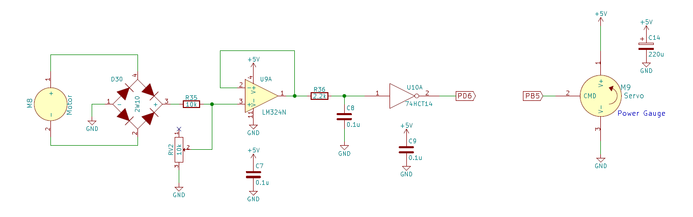
The crank interaction relies on the user spinning a brushed DC motor, which produces a voltage across its terminals. Since there is no guarantee which direction the user will turn the motor, its output terminals were connected to a full bridge rectifier to ensure only a positive signal can be produced, protecting the ICs.
The output of the rectifier is then run through a voltage divider consisting of a fixed 10k resistor connected to the positive output of the rectifier and a 10k potentiometer connected to ground. The common node between both is connected to a unity gain buffer (LM324N) whose output goes into a low pass filter. This prevents the impedance of the divider circuit from affecting the low pass filter tuning. The values of the C and R were chosen empirically, seeing what cutoff frequency would best squash the noise observed in the signal.
Finally, the analog signal went into a 74HCT14, which produces a digital output. The resistance of the 10k potentiometer was then tuned to determine at what speed the user would need to turn the crank to result in a transition (falling edge) from the 74HCT14.
A power gauge on the control panel provides a visual indication of the power level achieved by the user turning the crank. This gauge was actuated by a servo motor. While the servo theoretically requires a 5V pulse for control, using a 3.3V pulse worked well. The pulse width limits had to be adjusted.
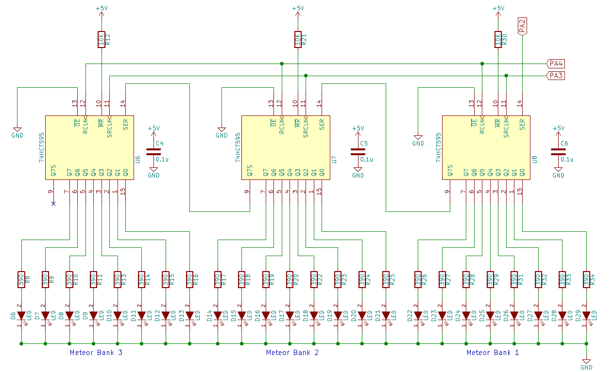
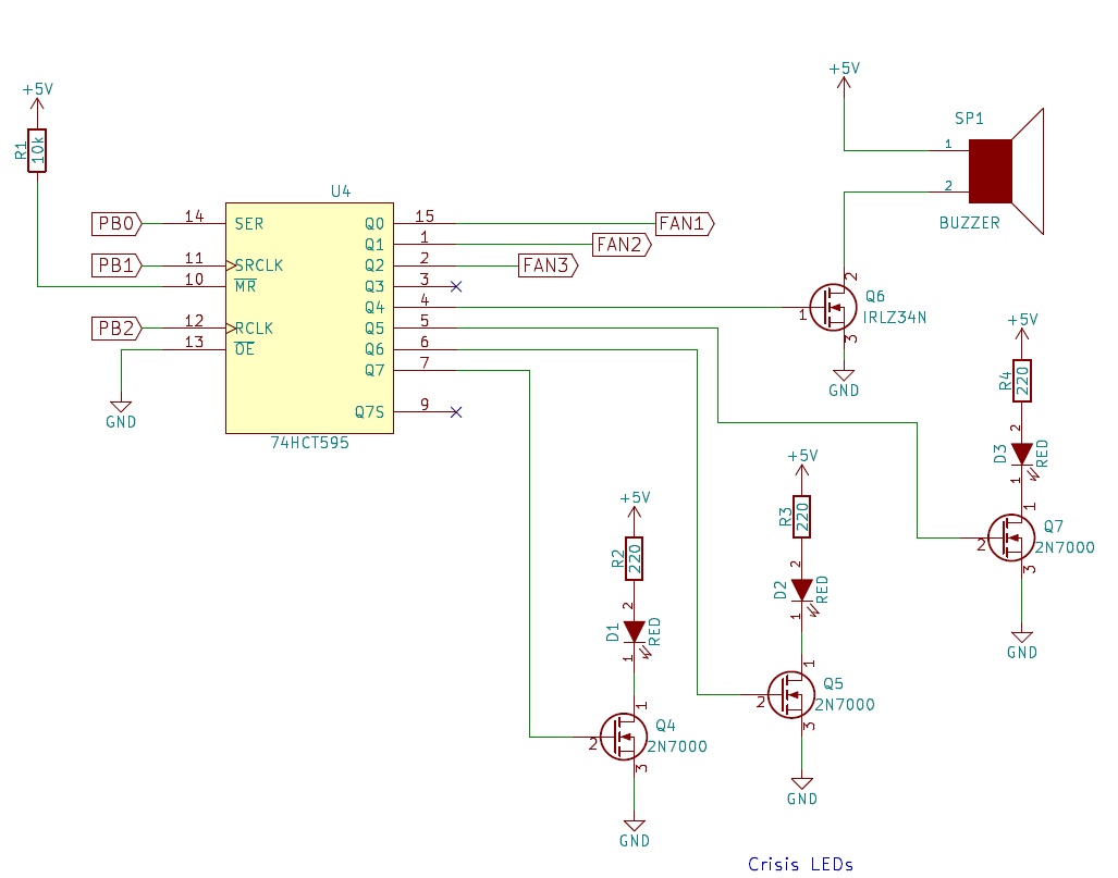
Falling meteorites are simulated using 3 banks of 8 LEDs each. In order to control these LEDs, 3 74HCT595 shift registers were cascaded to produce an effective 24 bit shift register. Each 595 is dedicated to a specific bank. Since the current being sourced into the LEDs is ~7mA, within the output limits of the 595, no transistors were required as the LEDs were connected directly to the outputs. The 390 ohm resistor were chosen to get a current of 7mA through the LEDs (Vf = 2.1V according to specs).
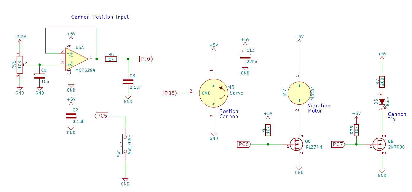
The cannon position is controlled by a potentiometer. The voltage at the sweep is the desired output signal to be read. In order to reduce the effect of power supply ripple (PSR), a 10uF capacitor was placed from the sweep to ground to act as a decoupling cap. The signal is connected to a unity gain buffer (MCP6294) into a low pass. This prevents the impedance of the divider circuit form affecting the low pass filter tuning. The low pass filter is used to help reduce any noise picked up by the cabling from the potentiometer to the breadboard.
The cannon is actuated by a servo motor, which is controlled with a PWM pin. The servo works with 3.3V pulses. The power to the servo motors is bypassed using 220uF capacitors near the servo's power terminals.
To fire the cannon, the user presses a momentary button. The button is wired directly into the TiVa, and the pin on the TiVa is set up using an internal pull-up. When the button is pressed a blue LED in the cannon tip is lit by turning on Q9. If the user shoots down the meteorite, the knob where the potentiometer is held, vibrates. This is controlled by turning on Q8, which turns on the vibratory motor. Both Q8 and Q9 require 5V for full saturation, thus pins PC6 and PC7 are set up as open drains. The gates for Q9 and Q8 are pulled up to 5V with 10k resistors. This ensures that when PC6 and PC7 are set high in software, Q8 and Q9 see 5V at their gates.
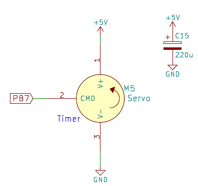
The timer display is actuated by a servo motor. The servo control signal is tied directly to the TiVa pin. The servo works with a 3.3V signal.
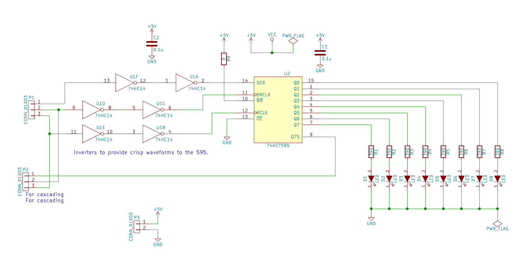
The warning LED and buzzer are controlled by a shift register (74HCT595). Due to the relatively high current demand of the LEDs and buzzer, low side drive was used, with the outputs of the shift register connected to the gates of the MOSFETs. To further save on pins, the first 3 outputs control the 3 fans of the air leak interaction.
The Air Leak game requires 3 hall switches, 3 fans, and 1 servo motor. The hall switches (digital) use an open drain output, which is wired directly into the TiVa, with said pins configured with internal pull-ups. Measurements were taken to ensure the rise-time was adequate.
The servo motor controls the oxygen gauge. While the servo theoretically requires a 5V pulse for control, using a 3.3V pulse worked well. The pulse width limits had to be adjusted.
The control signal for the fans comes from the same shift register that controls the warning LEDs.